This week we had to build a wireless and/or wired network with at least two nodes. I built a wired network using a bus with a bridge and two nodes.
First, I downloaded the traces and interior files for the hello.bus bridge and node boards from the class website.
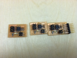
I then milled the boards and soldered the components onto them.
Once the boards were complete, I used my programmer to program each of the boards. With each program, I changed part of the code in order to connect each node with a different character input (0, 1, and 2) for the network. Below, is the change I made for the node I wanted to be connected with an input of "2."
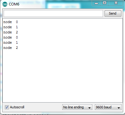
After I programmed each node (including the bridge), I connected each of the nodes to the bridge, which was connected to my computer through the FTDI connector. I opened the Arduino IDE and opened the serial monitor (under tools). Once inside the serial monitor, I pressed 0, 1, or 2 in order to see the LED flash. After I pressed 0, 1, or 2, all of the boards flashed simultaneously and then the board linked to that particular number flashed again. A video is below along with the accompanying activity in the serial monitor.